1Introduction
Strips Drip Oil detects leaks and tells water from oil. It has two sets of capacitive sensors. Along the long edges, an outer set reacts to any liquid and raises a flood alarm. In the middle, an inner set sits behind an oil-absorbing layer and a metal foil, which water and touch cannot pass. When the layer soaks up oil or another non-water liquid, it raises an oil alarm. Strips Drip Oil also measures temperature.
It is made for machine rooms, hydraulic systems and technical installations, under pipes, tanks and equipment. It works with any LoRaWAN network server (LoRaWAN 1.0.4, class A, OTAA) and reaches up to 10 km in line of sight. The battery is built in and lasts well over ten years. Alarms are sent confirmed.
What's in the box
- Strips Drip Oil, with the oil-absorbing foil and the adhesive already on
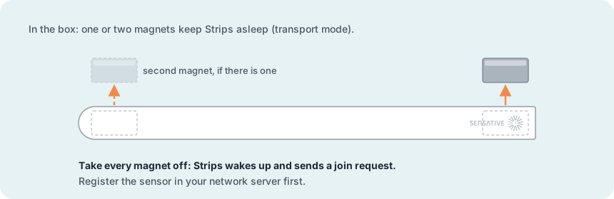
- One or two magnets on the sensor. They keep it in transport mode until you start.
- The LoRaWAN keys (DevEUI, JoinEUI and AppKey). They come on a label in the box and also by e-mail.
No tools or screws are needed. The +Clip mounting accessory is sold separately.
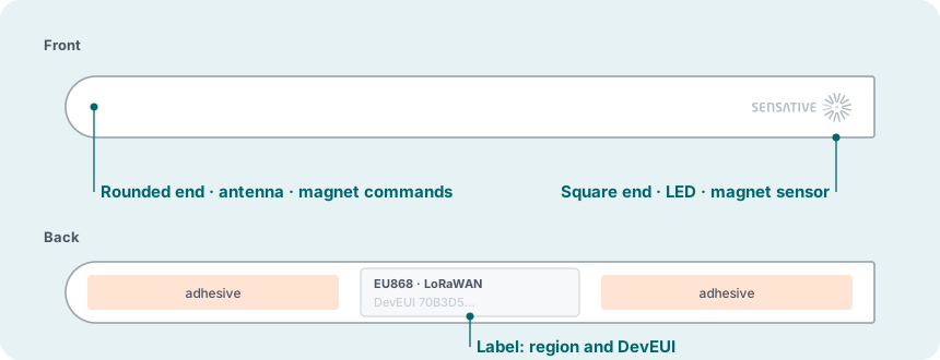
Parts of the sensor
2Before you start
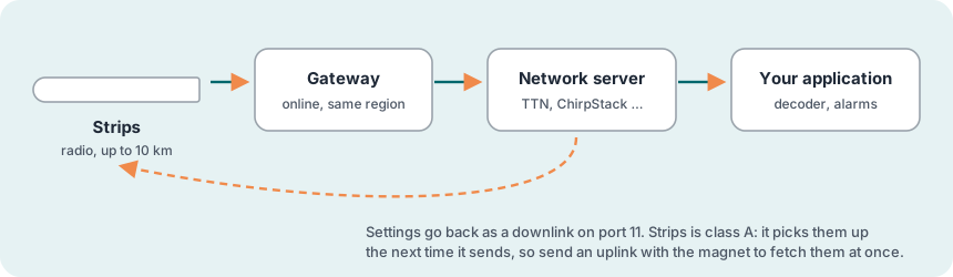
A LoRaWAN sensor needs a little more preparation than a sensor that pairs with a hub. Have this ready first:
You need
- A LoRaWAN gateway within range, powered on and online
- An account on a LoRaWAN network server (for example The Things Network, ChirpStack, Loriot or Actility), with the gateway added to it
- The keys for the sensor: DevEUI, JoinEUI (also called AppEUI) and AppKey
- The region printed on the sensor's label (for example EU868 or US915). The network server and the gateway must use the same region. In US915 and AU915, they must also use the same sub-band.
- The Strips payload decoder in your network server or application, so the messages can be read (see Support)
Choosing the place
- Where the leak will reach the long edges: flat on a floor, in a drip tray, or under equipment and pipes. Liquid is detected where it reaches the edges of the sensor.
- Temperature: the sensor works from −20 to +60 °C. Keep it away from very hot or very cold liquids and surfaces.
- Antenna: the rounded end holds the antenna. Keep that end off metal.
- Range: up to 10 km in open line of sight, much less through walls and floors
- No metal: do not mount Strips directly on metal, magnetic surfaces or inside a metal structure. If it has to go on metal, put padding between them.
3Step by step: from box to ready
Eight steps. Register the sensor in the network server before you take the magnets off. Then join it, choose what it should report, and mount it last.
Unpack
Check that the sensor and its magnets are there, and find the keys. Leave the magnets on until you join.
Register the sensor in the network server
- Add a new end device in your network server, with activation OTAA.
- Choose LoRaWAN 1.0.4 (MAC version), regional parameters revision RP002-1.0.1, and the frequency plan for the region on the label. In US915 and AU915, choose the same sub-band as the gateway.
- Enter the DevEUI, JoinEUI (AppEUI) and AppKey. Check them carefully: one wrong character and the join fails.
- Add the Strips payload decoder to the device or the application.
Join the network
Take every magnet off the sensor. Strips leaves transport mode and sends a join request.
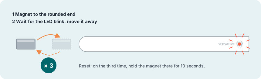
If the magnets have already been off, or you are joining the sensor again, start the join with the magnet instead: move it to the rounded end three times, for three green blinks.
Check the signal where it will sit
Hold Strips at the place where it will be mounted and send an uplink: move the magnet to the rounded end three times. Then look at the message in the network server.
Configure
From the factory, oil and liquid detection are off. Turn them on with the profile. The sensor calibrates itself two hours after the join, so mount it within those two hours (step 6). Step 7 explains when to calibrate by downlink instead.
| Profile in the Config Tool | What it does |
|---|---|
| Liquid, Oil Leak, and Temperature Alarm | Alarms (confirmed) for liquid, for oil, and for temperature below −10 °C or above +50 °C. The sensors are checked every 30 seconds. |
| Custom Profile (Advanced) | Choose reports and settings yourself, for example other temperature levels or the flood report. |
- Open the Strips LoRa Config Tool and choose Strips Multi-sensor +Oil.
- Choose a profile, check its reports and settings, and change a value if needed.
- Copy the payload the tool creates, and send it as a downlink on port 11 from your network server.
- Send an uplink with the magnet (three times at the rounded end). Strips is a class A device: it only receives a downlink right after it has sent something.
Install
- Make sure the surface is clean and dry, with no oil present.
- Peel off the transparent protective film on the back, which covers the adhesive.
- Press Strips Drip Oil flat onto the surface.
Where the adhesive is not enough, for example on a rough surface or where the sensor may need to be moved, mount it with the +Clip accessory (sold separately) instead.
Calibrate
The sensor calibrates itself two hours after the join. You only need to calibrate it yourself if it was not mounted, dry and free of oil at that time, if you move it later (different surfaces give different baselines), or after a leak, when it has been cleaned and given a new foil (see After a leak). Then, with the sensor in its place, dry and free of oil, send the downlink 030030 (hex), or AwAw (base64), on port 11, and send an uplink with the magnet.
Ready
- Registered in the network server with the right region and keys
- Joined, and the messages are decoded
- Profile chosen and confirmed with status code 0300
- Mounted dry and free of oil within two hours of the join, or calibrated by downlink
- Signal checked at the final spot
4Using the sensor
What it reports
- Flood alarm: any liquid at the long edges
- Oil alarm: oil or another non-water liquid in the oil-absorbing layer. While it is active, the LED blinks orange at regular intervals.
- Temperature: alarms at the low and high levels, reports or averages
- Heartbeat: with no alarms, one message every 24 hours, to show that it is online
Damp places: adjusting the liquid alarm level
In a damp place, the flood value (0 = dry, 100 = soaked) from the sensors along the edges can rest above 0, and with the default alarm level of 10 % the liquid alarm may trigger without a leak. Calibrate the sensor in place first (step 7). Then watch the flood value for a few days, using the Flood Report Interval (for example 60 minutes) to see it, and set the Flood Alarm Threshold Level clearly above the highest normal value, with a few per cent of Flood Alarm Hysteresis. Send the settings from the Config Tool as a downlink on port 11, then send an uplink with the magnet. Do not go higher than needed: a small leak must still pass the level. The oil alarm has its own level, the Oil Threshold, and is not affected.
Confirmed messages and network outages
Alarms are sent confirmed: Strips waits for an acknowledgement from the network server. If none arrives, for example because the gateway is off, Strips goes into resend mode. It tries again after 1, 2, 4, 8 minutes and so on, up to once a day. After 7 days without an acknowledgement, Strips resets itself and goes into standby (see below).
Operating modes
| Mode | What it means |
|---|---|
| Transport | Magnets on, deep sleep, almost no battery used. This is how Strips is delivered. |
| Joined | Normal operation: connected to the network and reporting. |
| Resend | A confirmed message has not been acknowledged. Strips retries with longer and longer gaps. |
| Standby | Not joined, after a reset or after 7 days in resend mode. Strips sends a join request once a day until it gets in. |
Strips cannot be switched off. Once the magnets have been removed, it can go back into transport mode only if it has never joined. This applies if the join failed, or if the magnets were put back before it sent a join request.
LED signals
| LED | Meaning |
|---|---|
| ● Short green | A magnet at the rounded end. An extra short blink after a three-swipe pattern: the command was accepted. Also shown when an alarm is acknowledged. |
| ● Long green | Joined, reset or starting up |
| ● Short orange | Strips is sending a report, or a join request when it is in standby |
| ●● Orange, then red | Duty-cycle limit: too many messages for the network. The message goes out a little later. |
| ● 5 short red | The join failed. After a resend: the message still had no acknowledgement. |
| ● 3 short red | Strips sent a confirmed report, but got no acknowledgement (ACK) from the network server |
| ● 2 short red | A report was not sent, because Strips is in resend mode |
| ● Long red | The magnet was detected while Strips is in standby (not joined) |
You can turn the LED down with the LED Level setting: all events (default), user actions and errors only, or very limited.
5Magnet commands
You give commands by moving a magnet at the rounded end of Strips. Use the magnet that came with it, or any small magnet.
| Command | How | Result |
|---|---|---|
| Send an uplink / join | Magnet to the rounded end three times, for three green blinks | A short extra green blink. If joined, Strips sends a message and picks up waiting downlinks. If not joined, it sends a join request. |
| Reset | As above, but on the third time hold the magnet at the rounded end for 10 seconds | Two long green blinks. Strips leaves the network and restarts. Its settings are kept. |
00 on port 11 (or 0100 on port 10). The sensor stays joined.6Maintenance and removal
Battery
The battery is built in and lasts well over ten years. It cannot be replaced. Frequent reporting, a weak link and high spreading factors all shorten it. To get the most out of it:
- Mount Strips away from metal, within good reach of a gateway
- Report only what you need. The profiles in the Config Tool are tested for battery life.
- Keep the poll intervals at their defaults unless you need faster response
In the cold, the battery level can read lower than it really is. This is expected: the reading takes the temperature into account and does not show the real charge.
The battery is a lithium manganese dioxide (LiMnO₂) cell, one of the most stable lithium chemistries. Do not open the sensor, and do not puncture it or heat it above +80 °C. When the battery is empty, dispose of the whole sensor as a battery, for recycling. Near the end of its life the battery normally swells a little; this is expected.
After a leak: new foil or a new sensor
The oil-absorbing foil can be used once. After oil has reached it, it must be replaced.
- After aggressive chemicals or extreme temperatures, replace the whole sensor.
- After ordinary liquids or dirt, clean the sensor and fit a new adhesive foil.
- Remove the sensor carefully. Saw gently with dental floss between the surface and the sensor. Do not pull the plastic housing away from the circuit board.
- Remove all the old adhesive, then clean the sensor with soap and water.
- Let it dry completely.
- Fit the new foil as described in the Strips Oil adhesive mounting guide (PDF): centre Strips on the foil, press the white cloth firmly against its sides, and remove the transparent film when mounting.
- Mount the sensor in its place again.
- Calibrate it again by downlink: with the sensor mounted, dry and free of oil, send
030030(hex) on port 11 and send an uplink with the magnet. The new foil and the cleaning change the base level, so this step is not optional.
Where there are oil mist, petrol fumes or a lot of moisture in the air, inspect the sensor regularly. These can soak into the sensor over time and affect its sensitivity.
Removing Strips
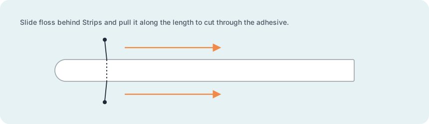
Use dental floss or a thin string.
Moving to another network server
- Delete the device from the old network server.
- Reset Strips with the magnet.
- Register it in the new network server and join it again.
The settings stay in the sensor.
7Troubleshooting
| Problem | What to do |
|---|---|
| Joined, but no oil or liquid alarms | Detection is off from the factory. Choose the Liquid, Oil Leak, and Temperature Alarm profile, and calibrate. |
| Oil alarm with no oil present | Calibrate again in place (downlink 030030 on port 11). Was the sensor moved, or was it not yet mounted when it calibrated two hours after the join? |
| The LED blinks orange regularly | The oil alarm is active. Check for oil and replace the foil. |
| Join Request in the network server, but no Join Accept | Check the region, the LoRaWAN version (1.0.4), the regional parameters and the keys. In US915 and AU915, the network server must use the same sub-band as the gateway. |
| Nothing at all in the network server | Check that the gateway is on and online, and listed as connected. Check that Strips is in range and not on metal. Check that the region on the label matches the network server. Strips may still be joined to another network server: reset it with the magnet and try again. |
| "MIC mismatch" | The keys are wrong. Check that they belong to this sensor and are typed correctly. |
| "DevNonce too small" | Delete the device from the network server and add it again. Then reset Strips with the magnet and join again. |
| A new setting has no effect | Strips receives the downlink at its next message, up to 24 hours later. Send an uplink with the magnet to fetch it sooner, and look for status code 0300. On a busy network it can take several messages before the downlink gets through. |
| Messages missing or irregular | Check RSSI and SNR. The sensor may be too far from the gateway, or behind metal. Some channels can also be disturbed by interference on the same frequency band, for example from a nearby cellular transmitter or an RFID reader. In US915 and AU915, check that the sub-bands match. |
| Short green, then short red | Duty-cycle limit: the network server thinks the sensor sends too often. The message goes out later. |
| Battery shows 99 % on a new sensor | That is full, by design. |
| Keys missing | They are on a label in the box and were sent by e-mail. Contact Sensative if you need them in digital form. |
| The LED does not react to the magnet at all | The battery may be empty. Check the last battery level the network server received. The battery cannot be replaced, so an empty sensor has to be replaced. If the battery level was fine, contact Sensative support. |
8Technical reference
For integrators. The Strips LoRa Config Tool builds the downlinks, and the payload decoder reads the uplinks. Both are linked under Support.
Ports and factory settings
| Port 11 | Configuration downlinks from the Config Tool. 00 returns all settings to factory defaults. |
| Port 10 | Commands. 0100 also returns the settings to factory defaults. |
Port 10, 08XXXX | Leave the network and wait: 08XXXX, where XXXX is a number of minutes as two bytes in hex. Strips leaves the network and sends no new join request until that time has passed; for example 0805A0 waits 1 440 minutes (24 hours). Useful for joining sensors at the office to check them before they are shipped to a customer for mounting. |
| Factory settings | Heartbeat once every 24 hours. Oil and liquid detection are off until you choose the profile and calibrate. |
| Class and activation | LoRaWAN 1.0.4, regional parameters RP002-1.0.1, class A, OTAA |
Status codes
After a configuration downlink, Strips answers with one of these codes:
| Code | Meaning |
|---|---|
| 0300 | OK |
| 0301 | Bad settings |
| 0302 | Bad payload length |
| 0303 | Value not accepted |
| 0304 | Unknown command |
Reports
| Report | Content |
|---|---|
| Flood Alarm | Liquid detected at the edges (confirmed) |
| Oil Alarm | Oil or another non-water liquid detected, or the other sensor was removed (confirmed) |
| Flood Report | The flood value, 0 = dry to 100 = soaked, at a set interval |
| Temperature Report / Alarm | Current temperature, and alarms at the low and high levels |
| Average Temperature Report / Alarm | Average over a set period, and alarms on the average |
| Battery Report | Battery level (%) |
Oil alarm values
The oil alarm carries a value that shows where the reading stands against the calibration:
| Value | Meaning |
|---|---|
| 0 | No alarm, stable against the calibration |
| 4 | Rising, but not past the calibrated level |
| 2 | Falling, but not past the calibrated level |
| 5 | Past the calibrated level and rising |
| 3 | Past the calibrated level and falling |
| 1 | Past the calibrated level and stable |
Settings
The settings that apply to Strips Drip Oil, as in the Config Tool.
| Setting | What it does | Range | Default |
|---|---|---|---|
| Flood Poll Interval | How often the leak (and oil) sensors are checked. 0 = off. | 0.5–60 min | 0.5 min |
| Flood Report Interval | How often the flood value is reported | 10–10080 min | 0 (off) |
| Flood Alarm Threshold Level | Flood value at which the leak alarm triggers | 0–100 % | 10 % |
| Flood Alarm Hysteresis | How far below the alarm level the flood value must fall before the alarm clears | 0–100 % | 4 % |
| Oil Threshold | Capacitive level that triggers the oil alarm. Different surfaces give different baselines. | 0–65535 | 1450 |
| Oil Filter Factor | Filter for detecting a deviation from the moving average. 0 = this detection is off. Recommended 5–15. | 0–30 | 0 (10 in the profile) |
| Oil Sensor Differential | How far the value must deviate from the filtered value to trigger an alarm | 1–100 | 30 |
| Temperature Poll Interval | How often the temperature is read. 0 = off. | 0.5–60 min | 2 min |
| Temperature Low / High Alarm Level | Temperature at or beyond which the alarm triggers | −20 to +120 °C | off |
| Temperature Alarm Hysteresis | How far back the temperature must go before a new alarm can trigger | 0.1–60 °C | 1 °C |
| Magnet Poll Interval | How often the magnet sensors are checked. All other intervals are multiples of it. Lower is faster but uses more battery. | 1–10 s | 1.5 s |
| LED Level | 0 = very limited, 1 = user actions and errors, 2 = all events | 0–2 | 2 |
9Specifications
| Sensors | Two-layer capacitive liquid sensor: outer for any liquid, inner (behind the oil-absorbing layer) for oil and other non-water liquids; temperature |
| Alarms | Liquid leak and oil leak, reported separately; temperature |
| Radio | LoRaWAN 1.0.4, class A, OTAA |
| Frequency plans | EU868 · US915 · AU915 · AS923-1 · IN865 |
| Range | Up to 10 km in line of sight |
| Battery | Built-in LiMnO2, 480 mAh, well over ten years |
| IP rating | IP67 |
| Operating temperature | −20 to +60 °C |
| Dimensions | 195 × 15 × 4 mm |
| Weight | 11 g |
| Mounting | Adhesive, or +Clip |
10Support
- Strips LoRa Config Tool, which creates the configuration downlinks: strips-lora-config-app.service.sensative.net
- Payload decoder (open source): github.com/Sensative/strips-lora-translator-open-source
- Support, FAQ and downloads: sensative.com/support
- Product page and product sheet: sensative.com/sensors/strips-oil
- Strips Oil adhesive mounting guide (PDF): sensative.com/assets/downloads/strips-oil-adhesive-guide.pdf
- Technical support request: through the form on the support page
Sources: Sensative Docs, Strips for LoRaWAN pages, FAQ Strips LoRaWAN, Troubleshooting Guide Strips LoRaWAN and +Switch (read 24 October 2026); Strips LoRa Config Tool (profiles, reports and settings); Rev B datasheets; specifications from the sensative.com product data.